Consistency Coupling

Consistency Coupling

This about the desire to keep things consistent.

When a development team makes a change to a component that is part of a large system they can be proud of their implementation. It can becomes the “way things are done”. The rest of the code base is shunned because it doesn’t follow the new standard. Now there is a desire to go through the rest of the system the improve it in the same way.

Stop, wait!

  • How long is this going to take?
  • When we the team get back to delivering business features?
  • Are these changes really needed?

These are the questions hiding in the background. These are the questions some delivery team will brush under the carpet.


I can totally buy the argument that if you change the look and feel of your application in one place there are good reasons to ensure consistency across the whole application. Your users may become confused by inconsistent interface.s They may stop using your software as a result.

What I don’t buy is the assumption that  consistency should stop you releasing a new feature. Perhaps you are trying something out that looks brilliant to the delivery team but when rolled out might causes your users to run a mile. In these circumstances the impact of the new feature should be measured. Only then will you know the true impact.

So when inconsistencies can impact you value stream I can be to swayed. But when I here technical arguments that say that we have to stop delivering new features for a while because this code change that was made to component A now need to be implemented across components B, C, D and E.

Often A, B, C, D, E are independent logical services. So the argument is saying because we changed A, we also need to change B, C, D & E. This same to contradict the assertion that services should be independent. Are we really arguing that the cost of changing one service increases exponentially as we build new service?  That makes no sense. We have a service based architecture to decrease costs not increase them.

Services communicate through interfaces to reduce implementation coupling

Services communicate asynchronously to reduce temporal coupling

Enforcing consistency across a code base causes build time coupling

I total empathise with the delivery teams OCD when they open up the code and see that services A and B have a terrible implementation when compared to services C’s elegant version. But in constantly evolving code base, the code will never be perfect at any point to time. You can never stop the clock and make everything perfect and even if you could, the moment time started running again the code would diverge and perfection would dissolve. In this way a code base demonstrates entropy. Over time and without a positive influence a code base will tend to disorder.

Dealing with this as technical debt. When improvements are spotted log them and even spend an hour or so improving  them yourself. But be cautious. If you have improved some code in a service that is not part of the feature set your team is working on that code may not be released in the short term. It may never get released.  It has no value if it is not released, so it is important to ensure that you don’t get distracted from the work you “should” be doing.

But lets follow this dark path a little bit more. Lets say you have invested the time and you want to realise the value of the work. Now you have to release this service alongside the rest of the team’s work. Ideally this would have little impact but experience tells me

  1. The release process will be very so slightly more complex
  2. There are more things to go wrong
  3. You get more questions about why “Service B” needs to be released when this increment is about changes service A

More effort, more time and more cost. You have coupled your change to the bulk of the team work purely for consistencies sake. Expand this problem to many services and you’re back to your monolith and you no longer can deliver cheaply, frequently and reliably. All this for consistencies sake.

If your application is such that you should drive for consistency at all cost –  you need to accept that impact and deal with the consequences – namely changes are likely to be slow. This should be a very rare case. If your priority is getting new features to your customer then you may have to deal with the fact that you application’s code may not be consistency.

The Scrum Master, Technical Lead Contradiction

The Scrum Master, Technical Lead Contradiction

It is not hard to find blog posts, whitepapers and books that describe Agile transformation. Many focus of the start point and then discuss the benefits that the transformation created. Often much of the detail in the middle is skipped giving the impression the time between the start and the end is insignificant.

In practice many organisations find themselves in a hybrid state, not one thing or another. They realise that they need to change and have started on that road. On the flip side, whilst many changes have been implemented, that same organisation would not consider themselves lean or agile. Whilst in this state valuable characteristics will emerge but it is just as likely that aspects will emerge that are the worst of both worlds.

This post is about a hybrid role that is sometimes found in this middle ground. The role of a Scrum Master / Tech Lead Roles

Context

The organisation is not yet convinced of Agile delivery. They have heard of Scrum but they can’t see why they need at full time person to coach each team. And the rates this person charges are so high they’d better find something else for them to do in the copious down time they’ll have!

Technical Lead

If you search for the term technical lead you’ll find many descriptions that range from project manager, architect to engineer. When you focus of on the common verbs in these descriptions you’ll find

  • Leads
  • Manages
  • In charge of
  • Accountable
  • Responsible

In a nutshell the Technical Lead often is expected to tell the rest of the team what to do and make all the technical decisions. Good technical leaders have the humility to delegate this to their team members but the results are the same, the rest of the organisation see the technical lead as the team.

Scrum Master

The Scrum Master on the other hand helps the team to understand the processes and frameworks they should use to reach the state of a self-organising team where they themselves make the decisions and work out what they need to do. Rather than leading from the front they are a Servant Leader helping the team become self-sufficient.

Conflict of Interests

As a team are learning the ways of any Agile framework they can be very fragile. During a transformation they will be asked to fundamentally change and yet still deliver at a sustained rate. Change can be stressful at the best of times but it can unbearable while you are under deliver pressure.

So, when the team is being coached by a Scrum Master who is also the Technical Lead that individual will have a very fine balance to find. They will be encouraged when their coaching effort generates visible improvement to the team. However it is inevitable that the point will come where some stakeholder will lean on the Technical Lead part of the role. The incumbent will have to step in to “take charge” due to some pressure or other perhaps to avoid a costly mistake. There is a good chance that this action can undo many of the team’s improvements. This intervention can shatter the team’s illusion that they are accountable and they fall back to the relative comfort of being told what to do.

A Scrum Master is trying to make the team accountable The Technical lead is the only one accountable. Hence the conflict of interest.

When forming a new agile team it is important that the coach is dedicated and not expected to be the defacto team leader. I would recommend to always have a dedicated Scrum Master but not everyone sees eye to eye with me on that. In that case it might be acceptable to give the Scrum Master role to one of the team members but only when they are a self-organising team for some time.


Silos – Agile Anti Patterns

Silos – Agile Anti Patterns

Last time I wrote about Work in Progress and why you should managed it to avoid creating bottlenecks. Silos cause bottlenecks. So this time I want to share my thoughts about why you often fine silos in a software delivery teams.

Organising a team around technology

In large organisations you might find IT functional units such as UX teams or database teams. The company organisation treats IT functions like business units. This might make sense on paper, but delivering software requires much tighter collaboration.

This results in each team focusing are their own work. The system they are part of is a secondary consideration. They tend to optimise themselves around their own workload. When this goes bad, the rest of the system becomes a customer.

You want this database changing?

Fill in this service request and we’ll get to it when we are ready!

Pressure to keep everyone in the team busy

Lets face it. Often the people who deliver software projects are not always seen as people. They are resources that need to optimising. You might feel a pressure from above to “make sure everyone is busy”. You must find new work to keep “resources” busy. The pressure comes from people striving for efficiency over effectiveness. Good results can only come from busy specialists because they “cost” the most. The motivation is financial rather than delivering a quality product.

What this does it increase the team’s work in progress as your specialists start more work to “get a head start”. When they finish their part, the value is not realised as the rest of the team catch up. The work stacks up unfinished.

We have to accept that people are expensive. A desire to maximise the return on investment will never go away. The answer, if you care about team effectiveness, is not to shape the work to fit the skillset in the team. Instead the answer is to fit the team to the work by encouraging generalists.

Lack of Definition of Done

The definition of done is a key elements in fostering team focus. It counters the individualism you find when a bunch of specialist come together. Without it you may experience the “Many type of dones”. The most common is development done where work is “thrown over the wall”. It is even more frustrating when the wall is a desk partition.

When a team of generalist form, and they focus of collaborating on a prioritise backlog. As the do so, the silos seem to evaporate. Everyone is busy although they might not be working on their preferred tasks. Project managers are not required as the team organises themselves around the work. There is no need for someone to move the work from person to person. And those that hold the purse strings have a warm feeling. The feeling that comes from predictability and knowing that no-one is under utilised.

Ignoring Work in Progress – Agile Anti Patterns

Ignoring Work in Progress – Agile Anti Patterns

What does Work in Progress mean?

Work in progress is a measure of the amount of work at a particular state of a workflow. What this means in practice is the amount of individual development tasks currently being undertaken by an individual or a count of how many widgets are at the same stage of a manufacturing process concurrently.

Why is it important and why shouldn’t it be ignored?

As it turns out, Work in Progress is a very important element in understanding the effectiveness of a team.  Experience shows that optimising the Work in Progress by determined an appropriate limit for each stage of a workflow can increase the rate at which work can flow through a workflow and therefore increase the effectiveness of a team. In effect, it encourages a team to focus on what is important at any given moment and reduces the impacts of context switching by limiting the amount of work being done at any point in time. Observing work in progress highlights blockers and bottlenecks clearly and obviously.

Given that this should seem like common sense to you it isn’t surprising that minimising work in progress features prominently in most “Agile” frameworks.

However, in practice common sense is not always applied.  In the wild you’ll often encounter teams that don’t manage their WIP limits. They will argue stubbornly that what you are suggesting, having the whole team focus of a small number of activities, is some sort of snake oil that will limit rather than improve the team. What you as an outsider will observe will include some or all of the following

  • Individuals seem busy but feel like they are never achieving anything. You will hear statements such as “I have not got any real work done today”. In fact they spend most of their time context switching.
  • Many pieces of work will be started but a lot less will be finished. There might be a sense that the team is on a death march and never gets to do the improvements that are desperately called for. Worst the team cost effectiveness may be in question.
  • Sometimes the result of a team rather than individuals dealing with too much work is a bottleneck later in the process. I often see this happens when there is an imbalance between development and testing. In order to eliminate the backlog of development work ready for testing stacking up, the work in progress limit for development should be reduced. In a multi skilled team this might free up enough people to clear the backlog quicker.

The first step towards minimising work in progress is to understand whether you have a problem. The simplest way to do this is to use a Kanban board and measure the number of items at a given status at any point in time.  It should be immediately apparent where the most work is occurring. It is then possible to set limits to ensure that the flow of work through the team’s process is maintained. Once you are comfortable with that a cumulative flow diagram provides a deeper view of the work flowing through a process over time. This might show for example that a Scrum team has too much work stacked up in “design” at the start of a sprint, and the same thing happens to work in “testing” at the end of the sprint. Using this insight, the team may self-organise themselves to limit these bottlenecks which results in a better flow overall.

Kanban CFD_1

That is the easy part. The hard part is getting the team to redistribute themselves to get the work flowing through and to avoid management types from thinking the key to optimising flow is by playing convoluted games of Resource Planning Tetris.


Asynchronous Stand-ups

Asynchronous Stand-ups

Working in distributed teams is always a challenge. This should come as no surprise as the Agile Manifesto contains the following

The most efficient and effective method of conveying information to and within a development team is face-to-face conversation.

During face to face interactions you are picking up subtle hints through all of your senses. If you try to have the same conversation over the phone or on a textual medium such as email or a messaging system it will take much longer, there will be more misunderstandings and there is a high likelihood that all parties will come away with a slightly different perspective.

Face to face communication is not always possible. Sometimes the team is spread out geographically or perhaps different members of the team have different working patterns. In this situation, you will need to face up to how the distributed team synchronises – which is usually the purpose of the Daily Stand-up. But what does the daily stand-up look like when no-one is in the same physical space?

Firstly, a brief reminder of the purpose of the daily stand-up meeting.  This link gives my favourite definition at the moment.

Stand-ups are a mechanism to regularly synchronise so that teams…

  • Share understanding of goals. Even if we thought we understood each other at the start (which we probably didn’t), our understanding drifts, as does the context within which we’re operating. A “team” where each team member is working toward different goals tends to be ineffective.
  • Coordinate efforts. If the work doesn’t need to be coordinated, you don’t need a team. Conversely, if you have a team, I assume the work requires coordination. Poor coordination amongst team members tends to lead to poor outcomes.
  • Share problems and improvements. One of the primary benefits of a team versus working alone, is that team members can help each other when someone encounters a problem or discovers a better way of doing something. A “team” where team members are not comfortable sharing problems and/or do not help each other tends to be ineffective.
  • Identify as a team. It is very difficult to psychologically identify with a group if you don’t regularly engage with the group. You will not develop a strong sense of relatedness even if you believe them to be capable and pursuing the same goals.

When working patterns or geographic locations are challenges some teams do stand-ups asynchronously. What does that look like?

Asynchronous stand-ups attempt to meet the same goals of a regular stand up. The main difference is that it is done textually, on a messaging system. As each team members starts their day they write up what they did yesterday, today’s plan and blockers. All other messages from other team members are there to be read. And that’s about it.

The primary benefits are

  • • Suits distributed workers – Each team member can work when it suits them. They have a high level of flexibility to fit work around their lives.
  • Acts as a permanent record – All the stand-up messages live in the message system for ever and can be reviewed later.
  • Easy to distribute the information – All it takes for interested parties to see what is going on is to view a Slack channel or subscribe to a distribution list.

However, these are secondary benefits. If you analyse Asynchronous stand-ups against the goals above you see that they don’t easily enable any of them well.

  • Share understanding of goals. The focus is on the person and not the work. The messages are often about “what I did” not about how the team’s overall goals are being met. It is also difficult for a Scrum Master to provide context about the team’s goals and progress towards them when required.
  • Coordinate efforts. Whilst it is possible to coordinate effort using a textual medium it is harder, especially if not all parties are online at the same time. Asynchronous stand-ups favour individual approaches to problem solving rather than a coordinated one simply because the communication medium resists it. When coordination is necessary the model breaks down as a call is usually required. The other problem is that if you are the first person to start the day you’ll be posting your message into an empty stand-up. You’ll need to check back to see other team member posts.
  • Share problems and improvements. If someone asks for help or someone spots that they can help there is often a delay from the problem being reported on the Async stand-up to the team being able to share it. Perhaps the team member with the problem posted their message several hours before the rest of the team started. Since then they have spent a of couple hours “barking up the wrong tree”, or they are not watching the messaging system for responses because they “are in the zone” or even that they finished for the day. This leads to inefficiencies that are not easily overcome.
  • Identify as a team. Attempts to synchronise asynchronously re-enforces an individualistic over a team approach. And if this is the only means for the team to synchronise then that sense of relatedness will be very hard to develop.

It is possible to make this work to some degree. It requires discipline and regular inspection to ensure it is giving the team what it needs. For starters set some expectations about when people should be posting updates to give the team a chance to coordinate. Secondly set some rules that enable the team to get some context before posting, e.g., update any tracking tools and view the burn down. The Scrum master could post some contextual information at the end of their day so at least the first poster in the following stand up has something to go on.

It’s not a good idea to go 100% asynchronous though. Instead arrange periodic conference calls or video conferences within the sprint boundary.  If you don’t keep things in check, laziness will creep in and before you know it the team are going through the motions. It is easy to spot when the quality of the messages goes down and team members show signs of not understanding the team’s overall goals.

Modern software development is a collaborative experience. With modern audio and video technology there is no excuse for not having regular synchronous communication within your team. Yes, there is a cost but how much do you value an effective team? There is no place for developers working in a silo hiding behind a messaging system like Slack. And if the team doesn’t want to communicate, it is probably not a problem with how you do stand-ups, the problem lies more with the makeup of the team.

There are a couple of other perspectives of Asynchronous Stand-ups below

Getting your arms around “Versioning”

Getting your arms around “Versioning”

Once you have spent some time integrating different systems you start to see the same problems coming up but being presented in different ways. The question I think I hear most often usually takes a similar form to this

We need to version this interface to avoid breaking an existing consumer, what is the best way to do it?

This is usually followed by some furious Googling and a lack of consensus.

In order to understand why this question keeps reoccurring and why there is no satisfactory resolution, it is useful to really break down the question itself.

What is meant by versioning?

Often the need for “versioning” is driven by the need to evolve the functionality of a service that is already live and is being consumed by at least one client. For whatever reason whether that be a bug fix or an enhancement, the change to the service is such that there is a risk of one or more clients failing to function after the change is made. It follows that “versioning” in its purest sense is the means to add the new behaviour to a Service without impacting existing consumers.

What do you mean by the best way to do it?

We are always looking for the best solution to any problem but the “best” solution is subjective. It depends on context and depends heavily on if we really understand the problem. There is also an assumption that a silver bullet solution exists that will deal with all eventualities but this usually proves to be false, especially in this context. The reality is that there are many approaches each with pros and cons and in this problem space you may need to apply multiple approaches.

Are we asking the right question?

The reason that versioning approaches are often incomplete or not successful is because there isn’t a “one size fits all” approach. In fact, versioning is not really the problem. Instead it is a potential solution to the real problem. We are not dealing with the problem of versioning. Instead the problem is

Minimising the cost of change

As you know change is the only constant. Clients and Services are in constant flux. We want to be able to make these changes (and to be able to run the resulting solutions) easily and cheaply without concerning ourselves with the impact. Some versioning approaches I’ve seen in the past are anything but cheap and simple!

Are you trying to solve a problem that already has a solution?

I have to admit whenever the question of versioning comes up I find myself Googling in the hope that someone has come up with a silver bullet since I last looked. I always draw a blank but what I notice is the same articles do come up time and again. Take a look at the index at this link.

https://msdn.microsoft.com/en-us/library/bb969123.aspx

If you start drilling into them you notice a common theme

  • A lot of clever people have done a lot of thinking in this problem space
  • Many of the articles are old (in IT terms)

Whilst things have moved on especially in terms of the cost of executing different instances of the same service side by side we don’t always have the luxury of being able to use all the latest tech and trendy architectural patterns on our project. So, the first step to getting a grip on this problem space is to understand that the problem is really about ensuring change is cheap and easy and reading about how people have tried to do that in the past.

Connecting Web Apps to external services – Virtual Appliance Walkthrough

Connecting Web Apps to external services – Virtual Appliance Walkthrough

For this purpose of this walkthrough it is assumed that the steps to establish a working Point to Site VPN have been completed. If you have also established a working Site to Site VPN following this walkthrough it will stop the it working correctly. The walkthrough assumes that the virtual network appliance is using the Barracuda NextGen Firewall F-Series virtual network appliance.

  1. Create an subnet in your VNET with the following settings Name:frontend and Address Range (CIDR Block) : 10.160.3.0/24
  2. Using the Azure MarketPlace create an instance of the virtual network appliance. This is a “Barracuda NextGen Firewall F-Series (PAYG)”. You will be charged for it use so you’ll want to ensure that these costs are factored into any planning. You are asked a number of things when setting this up. The important things for this walkthrough are that it is in its own resource group and it is connected to the frontend subnet you just created. Make a note of the password you use – it will be needed later.

fw1
Notice that you will be charge for the Barracuda License outside of any Azure Credit you might have.

fw2

  1. The Virtual Network Appliance needs to act as a network gateway, capturing traffic that is not address directly to it and forwarding it on to its destination. In order to do this IP forwarding needs to be enabled on the Network Interface for the Virtual Network Appliance.

fw3

  1. Create a Route Table that will route all Internet bound traffic to the virtual network appliance. In this example, I’m controlling the public IP so I’ll restrict the rule to just this IP. This means that I’ll still be able to connect to my VM over the Internet without issues. In production scenarios, you’ll have to think a bit harder about how the routes should be set up. Ensure that the route table is created in the network resource group.
  2. In the newly created route table create a route that routes traffic that needs to go through the virtual network appliance. Ensure that you have the following settings, Next Hop Type: Virtual Appliance & Next Hop Address: . If you are using a single IP remember you’ll still need to use CIDR notation. That means appending /32 to the end of the address.

fw4

  1. Assign the route table to the GatewaySubnet and the Backend Subnets.
  2. Through the service plan for the App Service, navigate to the networking option and then click to Manage the VNET Integration. Under the VNET Integration you need to add an entry to the IP ADDRESSES ROUTED TO VNET section. For this walkthrough you can set the start and end address to that of the external endpoint you are connecting to. For production scenarios use an appropriate address range. Take into consideration other services that the application might use, such as SQL Azure and Redis cache. By default all these connections are over the Internet so if you are not careful, you can route traffic for these connection into your VNET.

fw5

Configuring the Firewall

When the Firewall is setup up it will be secure by default and as such it will not know what to do with traffic destine to your external endpoint. Therefore, it will need to be configured to allow this traffic to flow. The Barracuda Firewall runs on Linux so connecting to it is a bit different to connected to a Windows machine. Luckily Barracuda provide a Windows Desktop application that takes away much of the pain.

  1. Download the Barracuda NextGen Admin application from the Barracuda website. You’ll need to create an account to achieve this. https://login.barracudanetworks.com/account/
  2. Once logged in go to Support -> Download and then select Barracuda NextGen Firewall project. On the resulting page select NextGen Admin as the Type and select the most recent version of the Barracuda NextGen Admin tool

fw6

  1. Run the NGAdmin tool and enter the public ip of the Virtual Network Appliance assigned to it by Azure. Then use Root of the username and enter the password you used when creating the appliance.

fw8

  1. The operation of the firewall software is broadly split into two roles. One for monitoring the system and the other for configuring it. If you click on the Firewall Tab at the top you’ll enter a screen that allows you to monitor firewall operations. From this screen you can do things such as seeing live and historic traffic cross the firewall and see what is allowed and what it blocked. On clicking the Forwarding Rules you can see how those access rules are defined. Luckily there is already a rule called LAN-2-INTERNET that manages access from the internal LAN (The Azure VNET in our case) and the Internet. The main problem is the software as it stands does not know the address ranges that represent our network. To change that we’ll have to use the configuration part of the software.

fw7

  1. Click on the configuration tab. The options to change the forwarding rules are very well hidden. Navigate to Box / Virtual Servers / S1 () [xxx] / Assigned Services / NGFW (Firewall) / Forwarding Rules

fw9

  1. On the resulting screen, you need to change the definition of the LAN-2-INTERNET rule. In the Source field you’ll find “ref: Trusted LAN”. If you drill into that by double clicking you’ll find that this in turn is defined as “Ref:Trusted LAN Networks” and “Ref:Trusted Next Hop Networks”. Again, by drilling in you’ll find that only “Ref: Trusted LAN Networks” is defined as 127.0.0.0/24. This is not sufficient for our needs.

fw10

  1. This rule needs to allow traffic that originates both from our VNET and from the VPN clients used to establish the Point to Site VPN from the App Services to the VNET. In production scenarios it would make sense to create groups to represent these address ranges and add them to the list of references defined by “Ref:Trusted LAN”. However, to keep things simple the rule can be updated directly.
  2. Add the address ranges 10.10.1.0/24 (Point to Site VPN Clients) and 10.160.0.0/16 (VNET) as sources. Note that the software locks down the UI to avoid mistakes creeping in. Therefore, you must Unlock the UI (by clicking LOCK bizarrely).

fw11

  1. Activate the changes by clicking “Send Changes” then clicking on “Activation Pending” and finally the “Activate” button
  2. This should be enough to browse from a VM on the backend subnet to the external resource. You can see traffic flowing from the Firewall tab under History. If the firewall is blocking traffic you’ll also see it here.

fw12

Connecting Web Apps to external services – Building a Simulated On Premise Network

Connecting Web Apps to external services – Building a Simulated On Premise Network

I mentioned last time that to test out the system that has been building up over the last few posts you need a simulated on premise network.  I briefly outlined that is was possible to copy many of the steps taken to build up cloud network to act as an on-premise network.

However, when I did this for real I was learning Amazon Web Services (AWS). So, this was the perfect opportunity to test out what I had learnt. The rest of the post is a walk-through I what I set up.

I’m not going to cover how to set up a Amazon account so I assume you have already done this. Amazon is slightly less forgiving when it comes to accruing costs so it is your responsibly to ensure that you choose free or cheap resources and that you delete things when you are done.

Secondly the walk-through builds up an IaaS based implement. The reason I do this is that it is closer to what you’ll find when integrating with an on-premise network for real. It is often useful to be able to have enough of understanding of the moving parts so that you can have productive conversations with the engineers working with the on-premise systems whose help you’ll need.

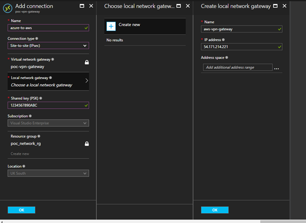
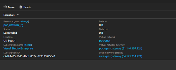
This walk-through will configure an EC2 instance running Windows Server on a VPC in AWS. The Windows Server will be running Remote Access Services (RAS) configured to act as an VPN endpoint. I use a T2 Micro sized EC2 instance to keep within the Free Tier in AWS. Before you can complete these steps you need two things from Azure, that this the Public IP address of your VPN Gateway and the shared secret you used when setup the Site to Site VPN in Azure.

AWS Configuration

  1. Log into the AWS and open up the VPC options
  2. Use the “Start VPC Wizard” and create a “VPC with a Single Public Subnet”. Note that a public rather than private subnet is used to keep the network configure simple and to allow RDP access to the EC2 instance over the Internet. Once the VPN is set up communication will be via a private IP address.
  3. For the IP4 CIDR block use 10.100.1.0/24. Give the VPC a name and use the same address range for the Public Subnet’s address range. The rest of the options can be left as their defaults.

Notice how similar this is to setting up an Azure VNET. AWS VPCs and Azure VNETs are equivalent. What the AWS VPC wizard does in the background is create an Internet Gateway and network routing which allows traffic from this subnet out on to the Internet.

Using the same address range for the VPC and the subnet is not something you’d do for real but it is enough for this demo.

  1. Open up the EC2 page and select Launch Instance
  2. From the list of Amazon Machine Images (AMI) select Microsoft Windows Server 2016 Base
  3. On the instance type page ensure t2 micro is selected, and click “Next: Configure Instance Details”
  4. On the Configure Instance Details page ensure that you change the network and subnet to the one created in Step 3. You also want to set Auto Assign Public IP to Enabled so we have the ability to RDP to the instance over the Internet. Everything else can be left at their default settings.
  5. Remember to either create or use an existing key pair in order to be able to get the EC2 instance’s Admin password.

It will take a few minutes for the instance to start and be at a state where you’ll be able to obtain the admin password. Once you have the password you’ll be able to RDP into it using the public IP it was assigned at startupaws1

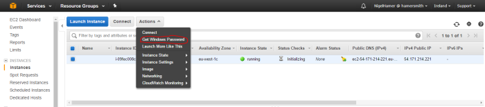
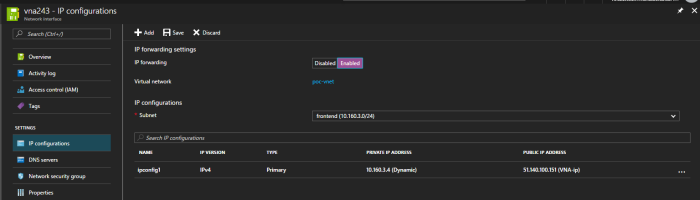
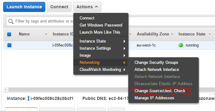
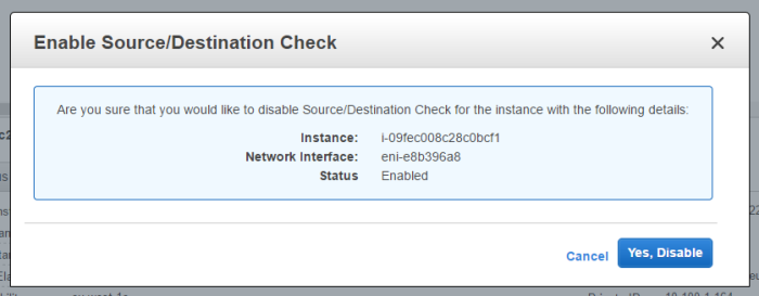
  1. Your EC2 instance will be acting as a network gateway which will allow network traffic destine for other resources to flow through it. AWS doesn’t allow that by default, but it can be setup by disabling source/destination checking.

aws2aws3

  1. Open RDP and connect to your windows EC2 instance as Administrator
  2. There is a script available here at that will install and configure RRAS on your server. It mentions Windows Server 2012 but it also works Windows Server 2016. It requires a few changes for the demo setup, so the updated script is included below.

# Windows Azure Virtual Network

# This configuration template applies to Microsoft RRAS running on Windows Server 2012 R2.

# It configures an IPSec VPN tunnel connecting your on-premise VPN device with the Azure gateway.

# !!! Please notice that we have the following restrictions in our support for RRAS:
# !!! 1. Only IKEv2 is currently supported
# !!! 2. Only route-based VPN configuration is supported.
# !!! 3. Admin priveleges are required in order to run this script

Function Invoke-WindowsApi(
    [string] $dllName,
    [Type] $returnType,
    [string] $methodName,
    [Type[]] $parameterTypes,
    [Object[]] $parameters
    )
{
    ## Begin to build the dynamic assembly
    $domain = [AppDomain]::CurrentDomain
    $name = New-Object Reflection.AssemblyName 'PInvokeAssembly'
    $assembly = $domain.DefineDynamicAssembly($name, 'Run')
    $module = $assembly.DefineDynamicModule('PInvokeModule')
    $type = $module.DefineType('PInvokeType', "Public,BeforeFieldInit")

    $inputParameters = @()

    for($counter = 1; $counter -le $parameterTypes.Length; $counter++)
    {
        $inputParameters += $parameters[$counter - 1]
    }

    $method = $type.DefineMethod($methodName, Public,HideBySig,Static,PinvokeImpl',$returnType, $parameterTypes)

    ## Apply the P/Invoke constructor
    $ctor = [Runtime.InteropServices.DllImportAttribute].GetConstructor([string])
    $attr = New-Object Reflection.Emit.CustomAttributeBuilder $ctor, $dllName
    $method.SetCustomAttribute($attr)

    ## Create the temporary type, and invoke the method.
    $realType = $type.CreateType()

    $ret = $realType.InvokeMember($methodName, 'Public,Static,InvokeMethod', $null, $null, $inputParameters)

    return $ret
}

Function Set-PrivateProfileString(
    $file,
    $category,
    $key,
   $value)
{
    ## Prepare the parameter types and parameter values for the Invoke-WindowsApi script
    $parameterTypes = [string], [string], [string], [string]
    $parameters = [string] $category, [string] $key, [string] $value, [string] $file

    ## Invoke the API
    [void] (Invoke-WindowsApi "kernel32.dll" ([UInt32]) "WritePrivateProfileString" $parameterTypes $parameters)
}

# Install RRAS role
Import-Module ServerManager
Install-WindowsFeature RemoteAccess -IncludeManagementTools
Add-WindowsFeature -name Routing -IncludeManagementTools

# !!! NOTE: A reboot of the machine might be required here after which the script can be executed again.

# Install S2S VPN
Import-Module RemoteAccess
if ((Get-RemoteAccess).VpnS2SStatus -ne "Installed")
{
    Install-RemoteAccess -VpnType VpnS2S
}

# Add and configure S2S VPN interface

Add-VpnS2SInterface -Protocol IKEv2 -AuthenticationMethod PSKOnly -NumberOfTries 3 -ResponderAuthenticationMethod PSKOnly -Name 51.140.107.124 -Destination 51.140.107.124 -IPv4Subnet @("10.160.1.0/24:100", "10.160.2.0/24:100", "10.10.1.0/24:100") -SharedSecret 1234567890ABC

Set-VpnServerIPsecConfiguration -EncryptionType MaximumEncryption

Set-VpnS2Sinterface -Name 51.140.107.124 -InitiateConfigPayload $false -Force

# Set S2S VPN connection to be persistent by editing the router.pbk file (required admin priveleges)
Set-PrivateProfileString $env:windir\System32\ras\router.pbk "51.140.107.124" "IdleDisconnectSeconds" "0"
Set-PrivateProfileString $env:windir\System32\ras\router.pbk "51.140.107.124" "RedialOnLinkFailure" "1"

# Restart the RRAS service
Restart-Service RemoteAccess

# Dial-in to Azure gateway
Connect-VpnS2SInterface -Name 51.140.107.124

It is surprisingly difficult to highlight within a code block in WordPress so review the IP addresses in the calls Add-VpnS2SInterface, Set-VpnS2Sinterface and Set-PrivateProfileString carefully.

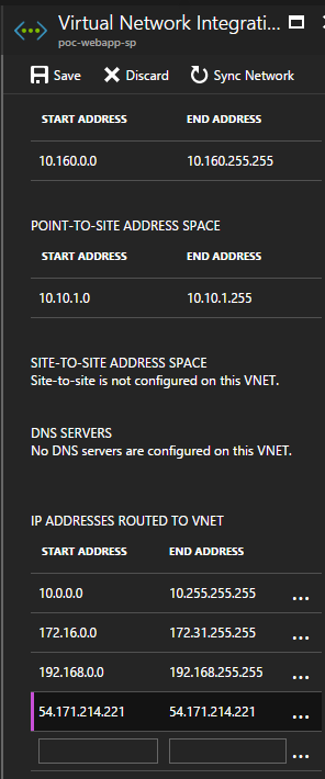
This script installs the RRAS feature. It then configures an interface which will allow traffic into the VPN. You need to define where the VPN will connect to, which is the Public IP address of your Virtual Network Gateway in Azure. You then need to define all the subnets that can be routed to via the VPN. In this case, we define the address range for the Gateway and Backend subnets. We also define the address pool for the Point to Site VPN. This will allow traffic that entered the on premise network from the App Services to flow back again. Finally, we use the same shared secret that set up on the Azure side.

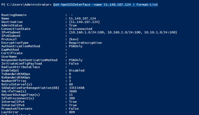
  1. Once the script has run you can confirms its status via the powershell command Get-VpnS2SInterface -name 51.140.107.124 | Format-List. The result should be something like this. Note that the ConnectionState will remind Disconnected until the Azure side is setup.

aws4

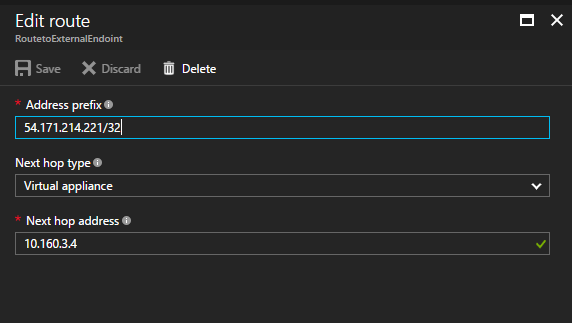
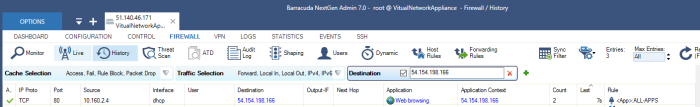
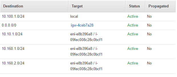
  1. You’ll need to set up routing rules which allows network traffic to flow correctly from the AWS VPC through the VPN connection. Open up the Route Table associated with the subnet you created and add the following routes. The routes tells AWS VPC to route traffic destine to the Azure VNET and App Services sitting at the end of the Point to Site VPN, through the EC2 instance running the AWS side of the VPN Gateway.

aws5

If you attempt to simulate an on-premise network in Azure by creating another VNET and VPN gateway and connecting that to the other side of the Site to Site VPN you also need equivalent routes.

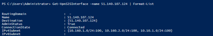
At this point if you have completed the Site to Site VPN configuration on the Azure side you should be set. Check that the Azure side VPN connection is reporting Connected and rerun Get-VpnS2SInterface -name 51.140.107.124 to see if the AWS side is happy.

aws6

Sometimes the RRAS service does not start correctly, so if you are having problems to run the command Connect-VpnS2SInterface -Name 51.140.107.124.

Connecting Web Apps to external services – Verifying a Site to Site connection

Connecting Web Apps to external services – Verifying a Site to Site connection

In this post, I’ll walkthrough how you test this configuration. Therefore are few moving parts so I take this a step at a time checking each connection.

Build a Test “On Premise” endpoint in Azure

To have a working example you need to have a “on premise” network at which you can point your Site to Site VPN. You don’t need a physical on-premise network – you can simulate it. I have done this both in Amazon AWS and in Azure.

To do this in Azure you repeat the steps for creating a virtual network, adding a VPN gateway and then configuring the Site to Site VPN. To avoid going completely mad use separate and appropriately named resource groups. When setting up the cloud side of the Site to Site VPN you point it at the public IP of the simulated on-premise VPN endpoint and do the opposite when configuring the cloud side VPN endpoint. Remember to use the same shared secret.

There are two extra steps you must remember which are required to ensure traffic can get back to the Point to Site clients, e.g., your web application. They are easily forgotten and the solution won’t work without them.

  • On the Local Gateway as well as adding the address space of Cloud VNET also add the Address range for your Point to Site Clients.
  • Add a route table so node son the “On Premise” network know what to do with traffic destine for the Point to Site clients. The next hop should be the Virtual Network gateway on the “on premise” side”

You’ll also need to add a VM to the simulated “on premise” network in order to provide an endpoint to hit.

Deploy a test app to App Service

These are the instructions to deploy an application using Visual Studio 2017.

  • Clone the following repo. https://github.com/nigelhamer/ConnectivityTest
  • Open this in Visual Studio
  • In Solution Explorer right click “Client” then select “Publish”
  • On the next screen ensure “Microsoft Azure App Service” is selected and select the option to “Select Existing”. [This assumes you created the web app described in a previous post.
  • Then click “Publish”
  • In the next screen select the appropriate subscription and Web App and click “OK”
  • This should return you to Visual Studio where the client is built and then deployed to the correct Web App.
  • Once this is completes a browser windows opens the web site you have just deployed. You see a screen as shown below. This error is there because we haven’t deployed the server yet, nor have we configured the client to connect to the correct server.

verify1

Deploy a Test app to VMs

These steps assume that you have a VM connected to the same Azure Virtual network that contains the VPN Gateway running your Point to Site VPN that is connecting to your Azure Web App.

  • Ensure that your VM has IIS setup and configured to running a .NET based Web Application
    • Install Web Server (IIS) Server Role
    • Add the Asp.NET 4.6 Feature
  • Disable IE Enhanced Security Configuration for Administrator
  • Build the Server project from the ConnectivityTest solution
  • Zip up the Server folder and copy onto the VM
  • Unzip the contents of the zip to C:\inetpub\wwwroot
  • Test the API is working by browsing to

verify2

Note that the response contains an IP address of ::1 for the caller. This is due to how the following code reports the IP of localhost. This reports the correct IP when the caller is not on the same machine as that hosting the API.

private string GetClientIp(HttpRequestMessage request = null)
{
    request = request ?? Request;

    if (request.Properties.ContainsKey("MS_HttpContext"))
    {
        return ((HttpContextWrapper)request.Properties["MS_HttpContext"]).Request.UserHostAddress;
    }
    else if (HttpContext.Current != null)
    {
        return HttpContext.Current.Request.UserHostAddress;
    }
    else
    {
        return null;
    }
}

Repeat these steps for the VM deployed to the simulated On-premise network

Verify Connectivity from the Web App to VM Service

In order for the Web App to talk to the VM in your Azure VPN you need to updates it configuration so it directs traffic to the private IP address of the VM.  Locate your Web App in the Azure portal and in its Application setting blade create an App Setting called BaseApiUrl. This overwrites the web.config application setting of the same name. You can also override the Name app setting in the same way.

verify3

Now when you load your Web App you should see a web page like this. This proves the Web Application is routing traffic from the Web App, through your VNET and onto the VM by way of the Point to Site VPN.

verify4

Referring back to the network diagram helps understand the significance of the IP addresses.

site2site(ips)

The first IP in my example is the IP address of the caller which in this case represents the Web App. Remember you have no access to the infrastructure that Microsoft is using to host this so this isn’t the IP address of the server running the web app itself. So, what is this IP address? When you configured the Point to Site VPN you configured an address range such as 10.10.1.0/24.  When Azure did its magic, it created a client that is used in the Point to Site VPN. So, the IP address, 10.10.1.2, is the address of the client and it is allocated from the client address range. Will it always be 10.10.1.2, maybe, maybe not. Will it always be an address from the range 10.10.1.0/24, yes it will. In fact, I have noticed that the IP of the client can change either side of a Web App restart.

The second IP address is the IP address of the server hosting the API. In this case it is the IP address of the VM sitting in the Azure VNET’s backend subnet. The address 10.160.2.4 comes from the address range of the backend subnet 10.160.2.0/24 that we use when setting up the subnet.

Verify Connectivity from the Web App to On premise

This step acts as the reveal. Over a number of point we have setup a bit a networking and two VPN connections. Whilst we have had to get our hands a bit dirty with a bit of network we haven’t had to get too intimate with network and routing details. And now if we go back to the Web App Application Settings and change the URL to the reflect the IP address of your on premise network the screen will change to show the IP address on the simulated on premise app server.

At this point you show now have an end to end working system.

Connecting Web Apps to external services – Site to Site VPN Walkthrough

Thanks for staying with me.

In this post I’ll be walking through the process for configuring a Site to Site VPN. This will be used to connect an on-premise network with the VNET that we have been building up in Azure. This will enable a Web Application hosted in Azure App Services to communicate to a web service endpoint hosted on premise entirely privately over firstly a Point to Site VPN connection and then a Site to Site VPN. In order to keep this post to the point I will only be discussing the work involved in connecting to the on premise network over a Site to Site connection. In a future post, I’ll describe the steps involved in creating a “Test” on premise network in order for you to see the Site to Site connection working in practice.

Lets revisit the summary diagram.

site2site(ips).png

Whilst in this configuration your application only needs to know the private IP address of the endpoint on the on premise network, you’ll need more in order to configure the site to site VPN. This requires the public IP address of the VPN endpoint in the on premise network. Likewise, configuring this will require the public IP address of the VPN gateway you configured in Azure last time. Armed with the public IP address of your on premise VPN gateway follow the steps below.

  1. Select the Virtual Network Gateway that you created last time and select Connections.
  2. Add a Connection. Give the connection a name and set the Connection Type to Site-To-Site (IPSec). Ensure the correct Virtual Network Gateway is selected and populate the Shared Key (PSK) field. By definition this key is used on both sides of the connection. Make a note of it so you can set up the on premise side later.
  3. You need to create a Local Network Gateway. This is a logical representation of the VPN Gateway on premise. Give it a name and use the relevant Public IP. You must specific the address space for the on-premise network. That enables Azure to configure the network routing to ensure on-premise bound network traffic is routed through the Site to Site VPN.

vpn gateway

It may take a few moment for the connection to be made. Eventually you’ll see a status of Succeeded.

vpn gateway connected

Once you have a successful connection you should be able to test it. Azure handles adding a routing entry so network address that are not Internet routable nor on the VNET will be routed through the VPN to the on premise network. Therefore, from a VM on your Azure VNET you should be able to ping a VM running on your on premise network via it’s private IP. This will work in the other direction too. Be sure to configure firewalls and network security groups to allow ICMP traffic.

Once you have confirmed the connectivity you should be able to configure your web application to connect to the resource endpoint on premise. Again you may need to tweak firewalls and NSG settings but in principle the connectivity should work.